
Main Page | Pictures | Blog
DCC: GP9M Decoder Installation | JMRI on PowerPC
Construction: Painting Track | Module Construction | Module Design
New Stuff!: For Sale HO Scale Walthers GP9M Decoder Installation
These series of pictures show how to install a T1
decoder in a HO scale Walthers Trainline GP9M
locomotive. The pictures were submitted to Train Control Systems [TCS] (http://www.tcsdcc.com) for use on their webpage, so the same pictures may appear there. (I retain copyright, but they are granted permission to use the pictures for their business.)
This inexpensive locomotive was produced
before DCC gained popularity, so the decoder has to be
hard wired.
For this installation, I used a TCS T1 two-function decoder.
Since I do not plan to have more than one accessory, I chose this decoder.
If extra lights or sound is desired, a more fully featured decoder may be required.
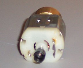
The first step in the process is to remove the weight
bar and motor. Be sure to mark the motor to remind
yourself which terminal is which. There's no
distinguishing marks on this motor to indicate which
terminal is which.
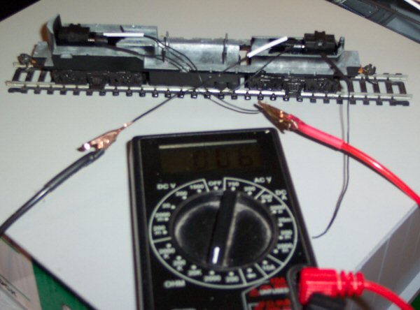
Next, since the pick up wires are both black, I used
some heat shrink tubing to indicate which ones pick up
from the right-hand rail (respective to the front of the
engine). I verified this by placing the
locomotive on a piece of track and measuring the
resistance with an ohm meter. A reading of close to 0
ohms means the wires connect. The meter in the picture is showing 6 ohms. (Not perfect, but close enough.)
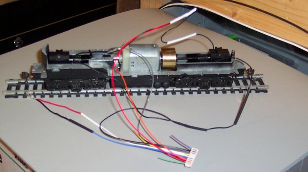
I followed the directions as to which wire went where,
placing heat shrink tubing on any solder joints.
After everything was connected, I then thought about
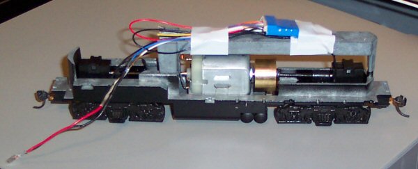
where the decoder would mount. Big mistake. I had tried to mount the decoder to the top of the weight bar,
which would not allow the shell to fit back on the chassis. Fortunately, I was able to move the decoder to the bottom
of the weight bar and complete installation.

Notes:
1. All wire-to-wire solder joints were made using a
Western Union Splice.
Simply overlap the exposed
wire at the halfway point and twist the left wire
around the right side, and the right wire around the
left. This method makes a very smooth joint, allowing
heat shrink tubing to easily seal the joint.
2. Trim your wires, but leave at least an inch extra
in case something goes wrong. I had a difficult time
with making the motor power connection and wound up
having to extend the orange wire.
Links
TCS - Train Control Systems Website
Western Union Splice
Home
Creative Stuff
Model Railroad Ice Rink
Computers
message board
Site Updates